[Day 19] Hardware Hacking Wiggles go brrr
USART
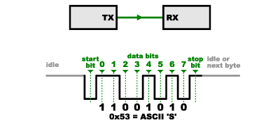
Universal Synchronous/Asynchronous Receiver-Transmitter (USART) or just simply “serial communication” or “async serial” uses two wires. One transmit (TX) data from device A to B and one is to receive (RX) data on A from B.
On USART the devices need to agree on:
- Communcation speed (baud rate)
- Bits per transmission (normally 8)
- Stop and Start bits
- parity bits
Example to transmit the letter “S”
Some USART devices uses additional wires like “Clear to Send” (CTS) and “Request to send” (RTS) to determine if the device is ready to send or receive. Also there might be a Ground (GND) to determine the voltage of 1 and 0.
SPI
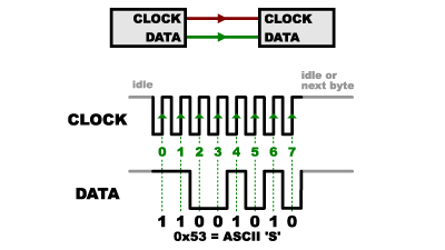
The Serial Peripheral Interface (SPI) uses an additional clock wire (SCK) which tells the receiver when to read the data line.
This increases the speed and reliability.
Only the controller sends a clock signal on the clock line. All other devices are secondary devices which must follow the controllers clock signal.
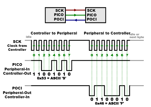
Two way communication
For two-way communication, two lines are used:
- Peripheral-In Controller-Out (PICO): Data sent from the controller to secondary devices
- Peripheral-Out Controller-In (POCI): Data sent from secondary devices to controller
Multiple secondary devices
To support multiple secondary devices there is another wire needed: Chip Select (CS) Every secondary devices needs to have an additional CS wire.
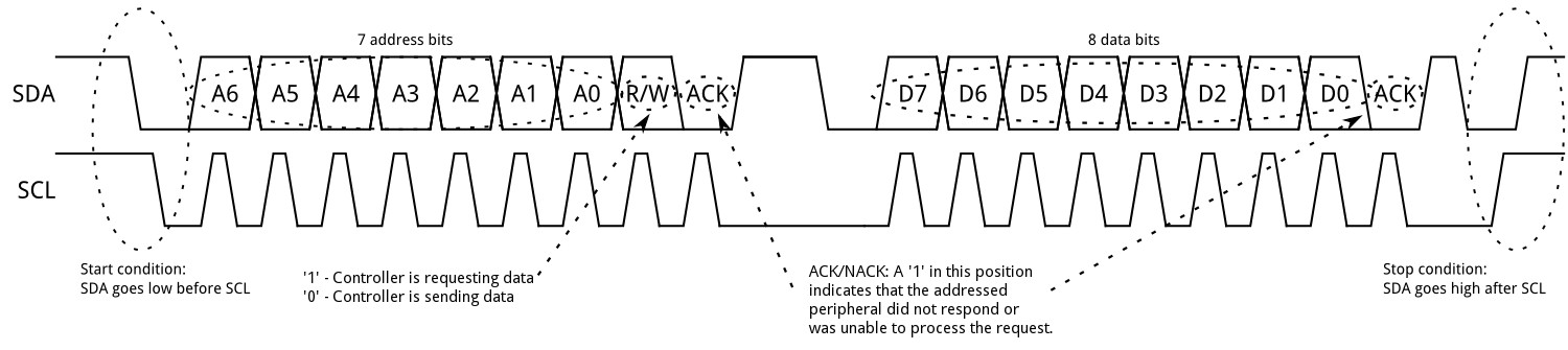
I2C
Uses Serial Data (SDA) and Serial Clock (SCL) to communicate. To select the secondary device I2C uses an “Address signal” on SDA instead of an additional wire as SPI. The “Address signal” supports up to 1008 secondary devices.
To prevent the devices talking on a busy line, Start and Stop signals are used.
Task
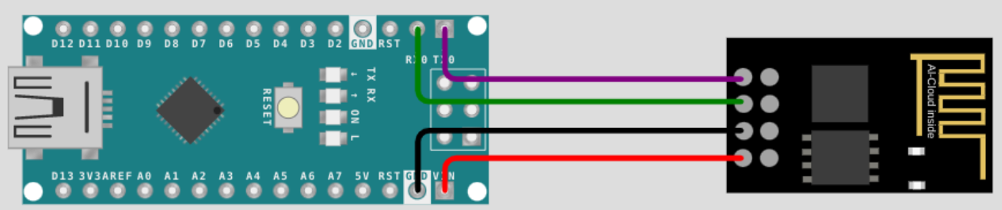
Black: GND = Ground Red: VIN = Voltage IN Black and Red are used to provide power to the chip.
Green (RX0 = Receive) and purple (TX0 = Transmit) are used for data transmission.
This looks like USART protocol.
Saleae
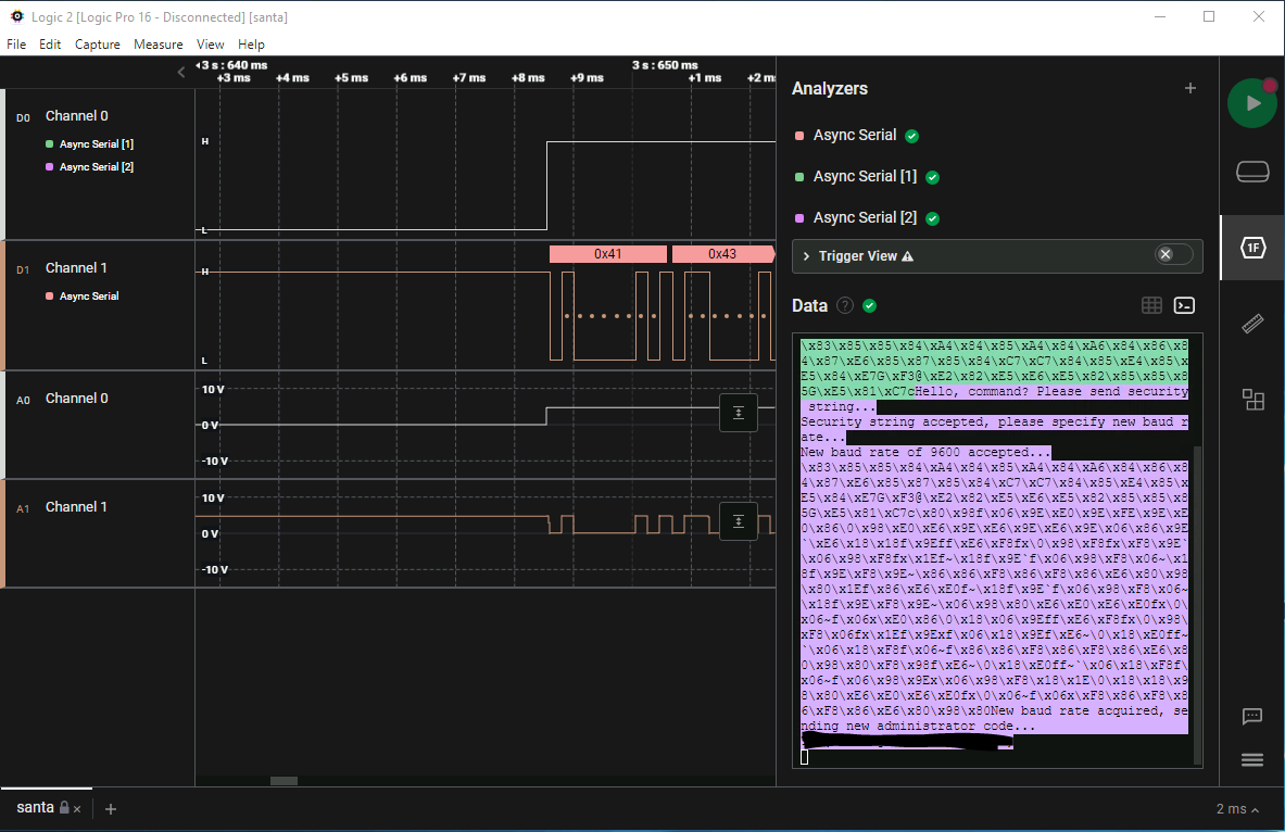
We use Saleae to analize a datadump from Logic Analyser.
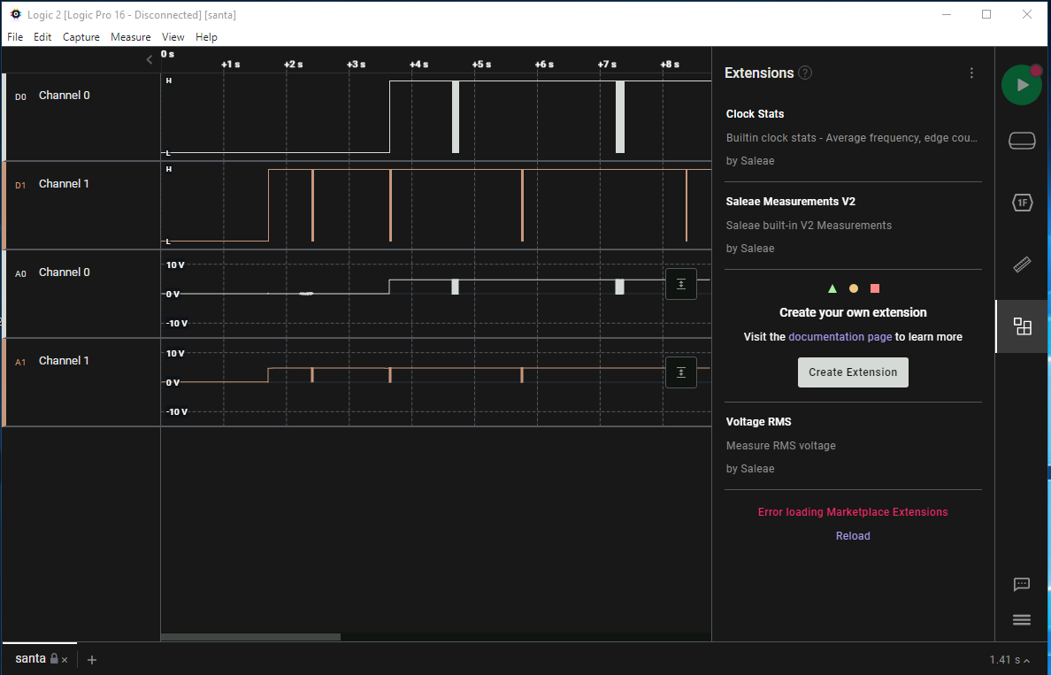
D0 and D1 are the corrected digitalized probes and A0 and A1 are the actual analgue data.
We look at the data sent over Channel 1:
For this we would need to tell Saleae at least which protocol was used (in this case Async Serial) and the Bit Rate (In this case 4800 Bits/s)
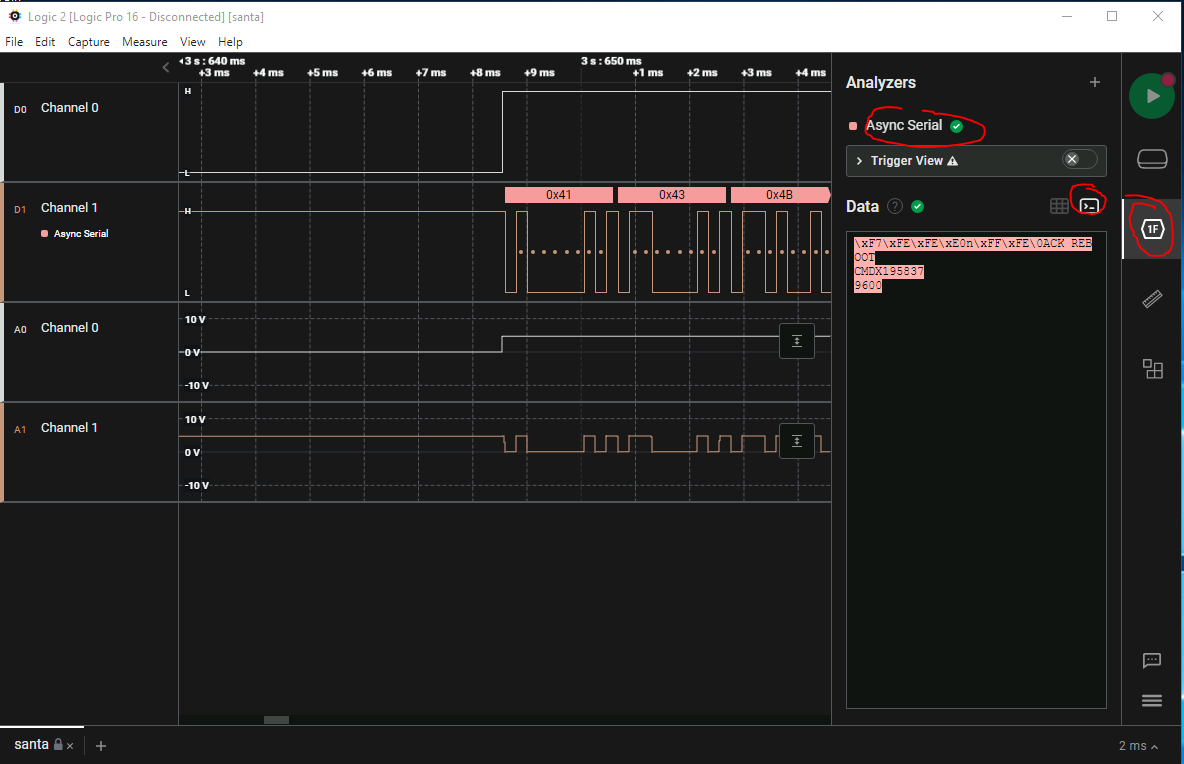
We see:
- ACK REBOOT
- CMDX195837
- 9600
Lets check the other line (Channel 0) by adding another Analizer but for Channel 0:
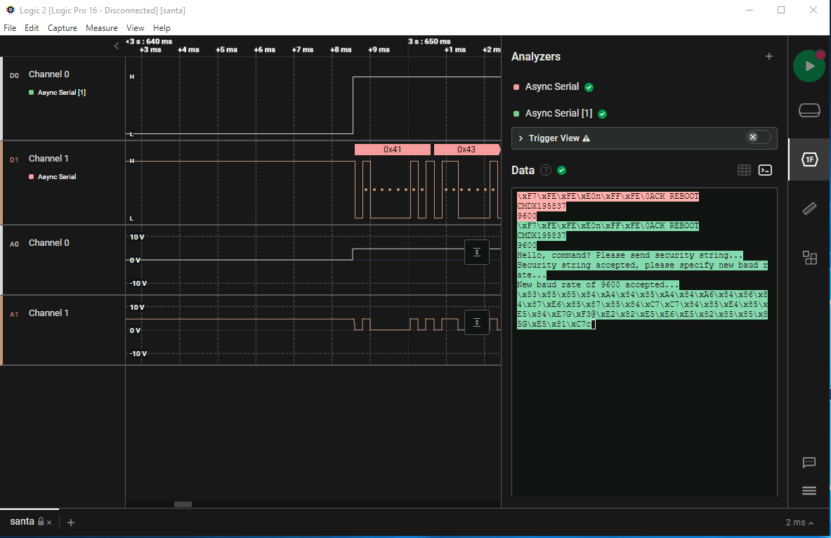
We now can see that they agreed on a new baudrate: 9600 and as we set it to 4800 we cannot see this data. Lets add another Analizer on the correct